|
|
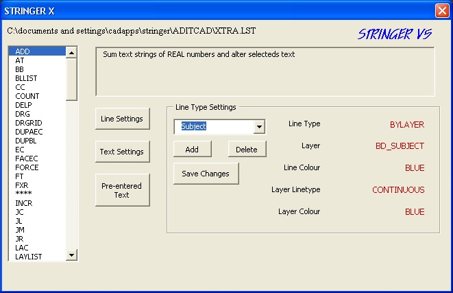
| ADD |
Sum text strings of REAL numbers
and altered selected text with result (optional) |
| ADJ |
Create Adjoining Lines by
Selecting Common Boundary |
| ADPI |
Add 180 degrees to Angle Text |
| AP |
Area Polygon Creation |
| AR |
Calculate and Write Area Text
Point to Point or by Closed Polyline |
| AT |
Align Text with another object,
either line or polyline segment |
| BAJ |
Perform Bowditch Adjustment on
Polyline of Traverse, based on the LDD points |
| BB |
Expand Bearings with Spaces |
| BLLIST |
Export Block names to a text file
called BLOCKS.LST in the current drawing directory |
| BRD |
Bearing and Distance Text Creation |
| CC |
Switch Last Entity Text Case Upper
to Lower and Lower to Upper |
| CHF |
Chamfer Command including Arc
Boundaries |
| CHLN |
Change an existing Line by
selecting Line with desired settings |
| CIRSZ |
Change Circle Sizes |
| COUNT |
Create Selection Set based on
Filters User Previous to
access selection set created |
| COUNT |
Create
Selection set with Filter |
| CTR |
Circle Trim, for removing segments
of lines inside the boundary corner circles. |
| CVT |
Calculate
and write Curve Text |
| DELP |
Delete
AEC Points using an existing Polyline as the selection window (by
Crossing) |
| DLAY |
Delete
all Objects on Layer of selected Object |
| DR |
Draw
by Orthometric + |
| DRG |
Draw a gate, replacing the line
selected |
| DRGRID |
Draw
a Grid on Current Layer |
| DTXT |
Create
Text by selecting desired Style from Style Menu File TEXTSTYL.DAT in
TEXTSTYL folder contains setup information |
| DUPAEC |
Scan for, and erase, duplicate AEC
Points that are |
| DUPBL |
Scan for, and erase, duplicate
blocks |
| EC |
Erase
Objects based on Filter |
| EXTN |
Extend Line, but create a new Line
for the extra length |
| FACEC |
Convert
3d Faces to Polylines. |
| FORCE |
Force
the COLOUR of selected Objects to the Layer Colour that they are on |
| FT |
Convert
Feet and Inches to metres |
| FTXT |
Select
Commonly used text strings from the menu and write them in the style
selected. File TEXTCONT.DAT in TEXTSTYL folder contains Text Strings |
| FXR |
Rectify
skewed rectangles |
| HD |
Horizontal
Distance |
| IB |
for
importing Block Attributes between Title Blocks |
| INCR |
Sets
up for auto incrementing Asks for text style |
| IPEX |
Create
Ipex lines by selecting an ARC or the linework leading to the truncation. |
| JC |
Justify
Text Centre |
| JL |
Justify
Text Left |
| JM |
Justify
Text Middle |
| JR |
Justify
Text Right |
| LAC |
Set
Layer Colour by picking an Object on the Layer |
| LAC |
Set
Layer Colour by selecting Object on Layer and entering the desired colour |
| LALT |
Set
Layer Linetype by picking an Object on the Layer |
| LAY |
Layer
manipulation menu |
| LAYLIST |
Export
Layer names to a text file called LAYER.LST in the current drawing
directory |
| LD |
Offers Line Style Menu, then
initiates the Line command" |
| LEN2PT |
Displays the distance to a point
on the selected polyline from the start |
| LISTXD |
List all Extended Data attached to
the selected Object (if any) |
| LN |
Offers Line Style Menu, then
allows entry of Bearings and
Distances for the linework. File LINESTYL.DAT in LINESTYL folder contains
setup information Allows for entry in Metres, Links, or Feet" |
| LNPEGS |
Line peg table |
| LOF |
Turn of Layer of Object selected |
| LST |
Simplification of List Lists brg,
dst, and layer of polyline sub sections |
| LSTTRAV |
Tabulates
the segments of the selected polyline as bearing and distance MTRIM |
| OFC |
Offset an Object and place new
Object onto CURRENT layer |
| PJ |
Join all Lines on the same layer
into a single polyline |
| PLD |
Offers Line Style Menu then
initiates the Polyline command File LINESTYL.DAT in LINESTYL folder
contains setup information |
| Q |
QIKPIK Multi talented programme
for setting/selecting options based on selected entiity |
| RADIATE |
Create AEC points by entering RAW
Survey observations, creating AEC Points |
| RDL |
Draw Radials for Cadastral Plans |
| RE |
Draws a paralelagram from a 2
sided polygon |
| REB |
Draws a rectangle based on the
centreline selected |
| RECT |
Draw a Rectangle |
| REPCARLSON |
Replace Carlson Attributed Point
with AEC point |
| REPPOINT |
Replace Attributed Point Block
with an AEC point. Attributes are DESC,
POINT, ELEV |
| RESC |
Rescale selected Blocks |
| ROB |
Change Rotation of Blocks |
| ROB |
Rotate Blocks by Adding an entered
amount |
| ROBS |
Rotate Blocks TO a forced angle |
| RSC |
Rescale. Set scale factor, then
select objects, base pt. Saves continually typing in scale |
| RT |
Reference Table Creation |
| SAME |
Make selected objects the same as
a datum object, including Layer, linetype, and colour |
| SCATRD |
Read ASCII file (as per scat) of
dummy,x,y,0,descr. Places Point at coord x,y and writes description |
| SCATTBL |
Read ASCII file (as per scat) of
dummy,x,y,0,descr. Tabulates coords with description |
| SD |
Slide Objects along the direction
of a selected Object |
| SD |
Slide. Select Datum line to use
for moving selected objects parallel to the datum line. |
| SETPL |
Fix Polylines for continuous
linetype |
| SETSC |
Set the current scale. Sets the
DIMSCALE variable |
| SHREP |
Shape
Replace Replace selected entity with a new block entity |
| SHTL |
Short
Line Table |
| SL |
Set
Line Style |
| SSC |
Create
Select Set based on Selected Polyline by CROSSING. Use Previous to use
selection set |
| SSW |
Create
Select Set based on Selected Polyline by WINDOW. Use Previous to use
selection set |
| ST |
Set Text Properties. After
selecting a piece of text which defines the style and height of the text
you want, you then select an object for its alignment, then enter your
text |
| SU |
Select a line or polyline segment,
then enter the desired azimuth of that line to set a UCS |
| SWCOL |
Changes the Colour (Bylayer or
Forced) of Objects to a different Colour, either ByLayer or forced. For
amending supplied information to suit your own In House colour
scheme," |
| TC |
Menu of Text Editing Routines.
Select Text first, then decide what you wish to do to it |
| TJ |
Text
join. Select base text then other text to append |
| TPC |
Place
TP Circles for Cadastral Plans |
| TRAV |
Traverse
Table Creation |
| TREX |
Automated Trim and Extend
programme, for when a supplied drawing has linework that does not
precisely intercept the boundary linework," |
| TRIBOUND |
Create
a Boundary around the 3d faces representing a Terrain Use PJ (polyjoin) to
finish |
| TROUT |
Create
KEAYS TR file of points |
| TRSET |
Set
tolerances for TREX |
| TRUN |
Truncation Routine, placing chords
around an ARC boundary |
| TSW |
Text swap, |
| TV |
Set value of selected text to same
as base text |
| TXT |
Select
Commonly used text strings from the menu and write them in the style
selected. Text Strings are in the file TEXTCONT.DAT in the TEXTSTYL folder |
| UC |
User Coordinate System |
| VAL |
Set PLAN rotation based on LINE
Resets to centre of screen and current zoom |
| W3DCO |
Write 3d Coordinates of selected
point |
| WCO |
Write Coordinate of selected
point. |
| XB |
Export
Block Attributes. Use in conjunction
with IB to reimport attributes |
| XRAD |
Export Radiations to external text
file. Just Uses snap modes, not AEC points |