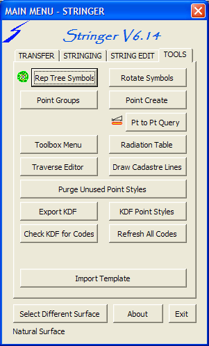
Replace Tree Symbols
|
Allows the user to add Tree blocks to the drawing based on
multiple parameters after the nominated code. You could have
"TR 0.5 7" as your code and have a Trunk symbol
inserted at scale 0.5 and a canopy symbol inserted at scale 7.
And you are not restricted to just one code. Here is a sample
of the TREEINFO.DAT file:
PT,VE_PINE,VE_TRUNKPINE,VE_SPREADPINE,VE_PINE_3D
BTR,VE_TREE,VE_TRUNK,VE_SPREAD,VE_TREE_3D
The first column is the code to look for, the second is the
symbol to use if only 1 scale is entered, columns 3 and 4 are
for when 2 scales are entered, and the 5th column for when a
3rd (height) scale is entered. The 3d symbol has XY scaled to
the spread scale and Z to the height scale, giving you a 3d
tree.
This is done based
on the settings defined in the Treeinfo.dat file.
|
Rotate Symbols
|
Allows the user to select points with symbols and nominate a direction
for those symbols. Good for aligning symbols with a roadway or feature
without the hassle of setting parameters.
|
Point Group Commands
|
 | Move - Allows the user to move a point group from a base point. |
| Rotate - Allows the user to rotate a point group from a base
point. |
| Scale - Allows the user to scale a point group from a base point. |
| HT Datum Shift
- Allow the user to change the elevation of a selected
point group by an entered amount |
| Set Elevation - Allow the user to change the elevation of a selected
point group to a nominated value |
| Compare Points to Surface - Allows the user to compare a point group to a
surface. The results are displayed on screen, but can be saved to an external
file as well. |
| Compare Points to Points - Allows the user to compare a point group to
another point group. Each point in the point group is compared to every point in
the other point group. Select point group _All Points to compare to
all other points in the drawing. If the subsequent distance is less than the tolerance then the
comparison is displayed and saved to the output file. |
| Surface RL to Points - Assign the surface elevation for the
XY of each of the points in the group. The subsequent elevation is applied
to the point in the group. |
| Chainage and Offset - Select an alignment
to tabulate the chainage and offset for all the points in the group.
Optionally export the chainage and offset to a comma delimited file. |
|
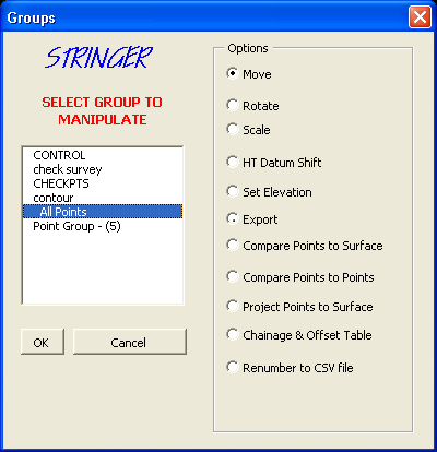
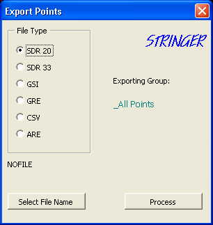
| Export - Allows the user to export a point group to file for upload into
survey data equipment. The file format available are: |
|
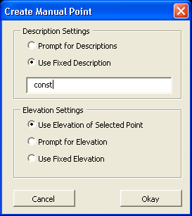
Create Point Manually
|
Similar to the Point Creation of Civil3D except this
method allows you to select 3D points and have the elevations reflect
the selection point |
 |
Toolbox Menu
|
Allows the user to access the Stringer X interface. Any of the Stringer X
commands can be selected from here. See the Stringer X
help for information
about the individual commands. |
Purge Unused Point Styles
|
The point styles defined in a Civil 3D project can use up valuable space in the
drawing. This command allows the user to purge any unused Point Styles
from drawing, it finishes by opening the AutoCAD Purge command. Unless point
styles are purged, Autocad will not purge any layers associated with point
styles. It is not desirable to perform this command prior to importing all survey data to the drawing. |
Export KDF (Key Description File)
|
Exports all of the entries in the KDF to a comma delimited text file for use
in other programs. |
KDF Point Styles
|
Creates a point style for all KDF entries which are set to default or
standard and assigning the new point style to the KDF entry. The new point
style uses the STANDARD point style for its defaults, but assigns the layer
from the KDF for the placement of the point style marker. If this method is
not used, whereby a point style marker is created for each KDF entry, with the
marker allocated to a particular layer, then the layer that is assigned via
the KDF can be purged by the Autocad purge command. This routine should be run
once on your template file so that all subsequent new drawings have a complete
point style listing. |
Check KDF for Codes
|
After the user selects a point code on the screen, the programme scans
through the KDF to find the associated entry for that code. It then checks
that the points label and point styles are up to date. Manual editing of point
codes causes the point to get out of sync with the KDF. |
Refresh Points
|
Due to the Key Description Data not being dynamic in Civil 3d, the points
can get out of synchronisation with respect to layers and scaling of symbols.
Selecting this command causes Stringer to scan all of the points to validate
their information against the Key Description Data. |
Import Template Information from External
File
|
Allows you to select another drawing or drawing template file from which to
import Blocks, Layers, Label Styles, Point Styles, Key Description Data, and
Point Groups. |